

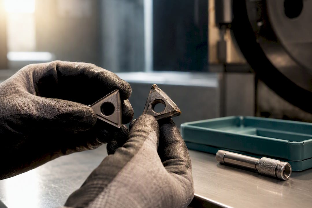
Track tool life by exporting CNC and PLC counters and condition signals into your Manufacturing Execution System, then act on remaining-life alerts to avoid breakage and cut tooling cost. Normalise the data through an edge or OPC UA layer, validate wear thresholds against a standard such as ISO 8685-1, and let the MES trigger replacement work orders automatically. Certain MES platforms are built for this task, turning scattered machine signals into a single, actionable view of tool condition across your shop floor.
TL;DR:
- Normalizing data with OPC UA or edge adapters is essential to accurately track tool wear signals across multiple machines.
- Condition-based tool-life management reduces unnecessary tool changes, lowering costs and increasing equipment availability.
- Layered monitoring methods, like spindle load, acoustic emission, and probing, improve wear detection accuracy depending on failure modes.
- Connecting machine signals to MES systems enables automatic work order generation, avoiding manual intervention and cycle disruptions.
- Pilot programs on two to three machines over four to twelve weeks help tune thresholds and validate cost savings before full deployment.
Fixed-interval tool changes waste good tooling and still let some inserts run to failure. A tool swapped after 400 parts because “that’s the schedule” might have another 150 good parts left in it, or it might have already started tearing your finish three cycles ago. Condition-based tracking replaces that guess with a number pulled straight from the machine.
The difference shows up in three places production managers already measure:
Schlote demonstrated the scale this works at: the company pulled tool-life counters and NC/PLC data from up to 65 SINUMERIK 840D machining centres into a single dashboard, giving cross-machine visibility that no single control panel could offer on its own. Careful measurement and threshold tuning can also extend usable tool life and cut tooling costs once a shop moves past guesswork. None of that visibility means much sitting in a standalone dashboard, though. It needs to reach the system that schedules work orders and tracks quality before it changes anything on the floor.
Every monitoring method trades cost against accuracy, and the right layer depends on what’s failing, not what’s fashionable. Start cheap, add fidelity where the failure mode demands it.
Spindle-load trending is the sensible baseline. It uses data your CNC controller already generates, and spindle motor current or torque trending can catch 70 to 80% of progressive wear events in roughing operations without adding a single sensor. Set thresholds as a rise over baseline load rather than an absolute value, since baseline varies with material batch and coolant condition.
Beyond that baseline, three methods each solve a specific gap:
A layered strategy keeps hardware spend proportionate: always-on spindle-load monitoring across every machine, AE or smart holders on the tools that actually break unpredictably, and probing reserved for parts where geometry is the real risk.
A spindle-load layer that catches most wear events and flags the rest for operator inspection beats a perfect system that takes eighteen months to commission.*
Getting from raw machine signal to an automatic replacement work order is a data plumbing problem before it’s an analytics problem. The path looks like this:
Pro Tip: Add a safe-state check (spindle stopped, axes at a known position) before any automatic swap command fires. It’s a small rule that prevents a very expensive mistake.
Run a pilot before touching the whole fleet. Pick two or three machines running your highest-volume part family, ideally ones already producing decent CNC counter data, and give the pilot four to twelve weeks depending on cycle volume.
Technical prerequisites to confirm before you start:
Validation matters more than most pilots budget for. Basic in-control tool counters can serve as a pragmatic first data source, but the thresholds built on top of them need statistical grounding. A mean-plus-sigma approach, flagging a warning at roughly three standard deviations above baseline and an action threshold around five, keeps false alarms manageable while still catching genuine wear trends.
Reconcile system counters against physical tool checks and operator confirmations weekly during the pilot. Track downtime reduction and unscheduled change frequency as your two headline metrics, then expand once both numbers move the right way.
This is an example architecture for some MES platforms: live KPI dashboards pulling directly from connected equipment, tool-life and downtime data sitting alongside quality metrics, and AI-driven suggestions flagging where a threshold or schedule needs adjusting. You get one screen instead of five spreadsheets.
A typical demonstration of an MES platform includes a live connectivity check against your own equipment, a dashboard tour showing tool-life and OEE data side by side, and an outline of what a pilot on your floor would look like. If you want to see how it applies to your specific machine mix, the Mestric™ solution page is the place to request one.

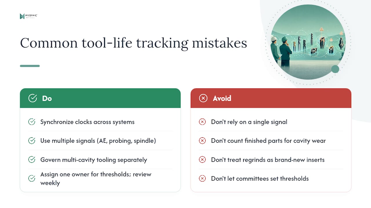
The technical setup is rarely what sinks a rollout. Unsynchronised clocks are the quiet killer: a tool-wear event logged three minutes off from its work order timestamp corrupts your cost-per-part data without ever throwing an error. Relying on a single signal is the second trap. Spindle load alone won’t catch chipping, and teams that skip the AE or probing layer end up “surprised” by failures their own data was already gesturing at.
Multi-cavity tooling deserves its own governance rule: counting finished parts hides a blocked cavity wearing three times faster than its neighbours. And regrinds need explicit handling, since treating a reground insert as brand new resets a threshold that should have started lower.
Put one person in charge of setting and revising thresholds, not a committee. When operator judgement and sensor data disagree, log both and review weekly rather than letting either side win by default. Automate the reconciliation job itself once the pilot proves stable, and keep watching that reconciliation rate as its own KPI. It’s the number that tells you whether operators still trust the system.
Most teams get to this point already running some tool-life data, scattered across CNC counters, a spreadsheet, and someone’s memory of “that machine that always eats inserts.” Certain MES platforms are designed to pull that data into one place without months of integration work first.
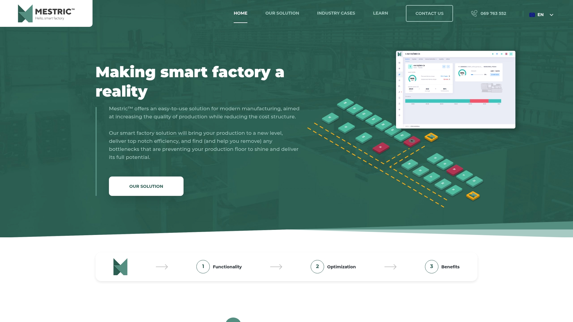
A demonstration of the MES platform covers a live connectivity check against your own machines, a walkthrough of the KPI dashboards showing tool-life and downtime data together, and a proposed pilot scope sized to your production line. Expect the pilot itself to surface concrete numbers on unscheduled tool changes and tooling cost per part within weeks, not quarters. If you’d rather see the platform’s full feature set first, the Mestric™ MES page lays out what connects to your equipment and how the AI-powered recommendations work. Book a demonstration and bring your worst-performing tool as the test case.
Tool-life tracking is the practice of monitoring wear on cutting tools, inserts, dies, and moulds using machine and sensor data, then feeding that data into production systems to schedule replacements before failure. It replaces fixed-interval changes with condition-based decisions grounded in actual signal data.
Spindle-load or motor current trending is the standard starting point because it uses data your CNC controller already produces and needs no extra hardware. It can catch a large majority of progressive wear events in roughing operations, with acoustic emission, probing, or smart holders added afterwards for chipping and geometric checks.
A focused pilot on two or three machines usually runs four to twelve weeks, long enough to gather a meaningful sample of wear events and tune thresholds. The timeline depends heavily on cycle volume and how quickly your team can reconcile system counters against physical tool checks.
A standalone dashboard shows you tool condition, but it can’t act on it. MES integration links that condition data directly to work orders, so a remaining-life alert automatically triggers a replacement request instead of relying on someone noticing a chart. Some MES platforms are built specifically to close the gap between machine signal and shop-floor action.
Certain MES platforms connect directly to shop-floor equipment and consolidate KPI, downtime, and condition data into real-time dashboards, which fits naturally with tool counters and spindle-load signals already available on most CNC controls. Pricing and technical scope for your specific machine fleet are available by requesting a demonstration through the Mestric™ solution page.


 069 763 552